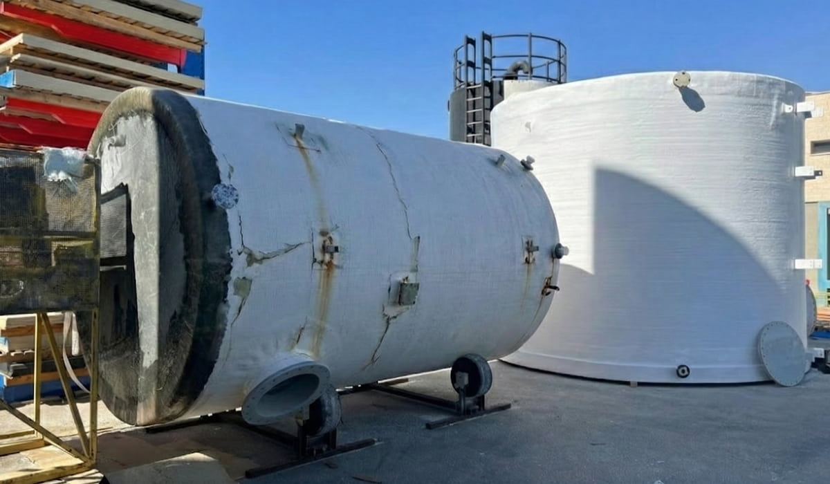




Plast Hen has designed and fabricated thermoplastic and fiberglass tanks and piping in Beersheba since 1993 under an ISO 9001 quality system. On projects where process piping meets a tank, nozzle diameter and gasket selection are only part of the specification. The governing question is the load path: where a load starts, which components carry it, and whether it ends in the structure or in a comparatively flexible tank wall.
Why is a tank wall sensitive to piping loads?
A tank is primarily proportioned to hold its contents. Hydrostatic pressure is distributed over a large shell area. A nozzle, by contrast, introduces concentrated loading at an opening that interrupts shell continuity. The region around that opening needs a local check in addition to the general wall-thickness calculation.
This distinction is especially important for thermoplastics because stiffness and long-term strength depend on temperature and loading duration. A modest sustained reaction can become significant through creep. In FRP, fibre direction and laminate construction govern how load spreads around an opening, so local reinforcement must be integrated into the laminate design. Our overview of thermoplastic and fiberglass tanks explains the material families; this article focuses on their mechanical interface with piping.
 If an unsupported line can be moved by hand and the tank nozzle visibly follows it, stop and review the load path before commissioning
The six load components at a tank nozzle
“Piping load” is not an adequate design input. A connection can receive three forces and three moments: an axial force, two transverse shear forces, torsion, and two bending moments. They need a stated coordinate system, sign convention and unit set.
| Component | Typical source | Potential local effect |
|---|---|---|
| Axial force | Thermal growth, line anchor or expansion-joint reaction | Pushes or pulls the nozzle neck |
| Vertical shear | Pipe, liquid, valve or strainer weight | Loads the weld and shell downward |
| Horizontal shear | Misalignment, wind, vibration or structural movement | Displaces the nozzle laterally |
| Bending moment | Heavy component on a lever arm or remote support | Rotates the flange and concentrates shell stress |
| Torsional moment | Line rotation or operation of an attached component | Twists the neck and joint region |
| Cyclic action | Filling, draining, pump operation and heat-up cycles | Promotes fatigue, loosening and unstable sealing |
These components are reviewed by load case rather than only at normal operation. Relevant cases may include empty, full, filling, draining, cleaning, maintenance, design-temperature excursions, emergency shutdown, wind and seismic action. A manifold piping system can produce different reactions as branches and valves change state even when its physical arrangement remains unchanged.
For tank nozzle piping loads, maxima should not be combined mechanically when they come from different operating cases. The interface schedule needs one row per credible case, preserving component signs, temperature and fill condition. This prevents both an impossible over-conservative combination and the accidental omission of the governing simultaneous reactions.
Dead weight and heavy valves need an independent support path
A heavy item near the tank should have a load path that does not terminate in the shell. Valves, actuators, flowmeters, strainers, long vertical runs and liquid-filled pipe add both weight and lever arm. As the distance between the component’s centre of gravity and the nozzle increases, the bending moment rises.
The first support is selected from geometry, material, temperature, line weight and maintenance needs, not from one standard distance copied between projects. It may be a floor support, bracket, hanger, guide or directional stop. Each choice restrains some movements and permits others, so support type matters as much as location.
Pipe material also changes the response. PP, HDPE and PVDF lines have different temperature behaviour and support spacing from metal piping. An industrial piping contractor should provide support reactions and nozzle loads to the tank fabricator rather than assume that plastic flexibility will absorb every mismatch.
A piping support near tank nozzle locations must also remain maintainable and active after filling. A shoe that lifts clear, a guide installed with no movement allowance, or a bracket attached to a structure that settles differently can recreate the reaction that the support was intended to remove. The support arrangement should therefore be inspected as part of commissioning, not only on the fabrication drawing.
Thermal movement requires controlled flexibility
Piping changes length with temperature. The tank also expands, contracts, and may move its nozzle slightly between empty and full conditions. If a line is locked between rigid anchors, the movement it cannot make is converted into forces and moments at the connection.
Possible measures include rerouting, flexible legs, expansion loops, sliding supports, spring supports or a suitable flexible connector. None is universally correct. An expansion joint installed without accounting for pressure thrust and anchorage can exchange one nozzle load for another. A short, overly soft connector can permit sagging, misalignment, or vibration.
For thermoplastic piping, thermal-expansion analysis must be coordinated with fabrication and installation practice. Our guide to plastic pipe welding covers joining methods, but a sound weld does not compensate for a restrained layout. A connection can be fabricated correctly and still receive reactions outside its approved design envelope.
For an HDPE piping system, material flexibility changes how movement is distributed; it does not remove the need for deliberate guides and anchors. PP and PVDF require the same systems view, using their own stiffness, thermal behavior, and service conditions rather than a support pattern copied from another material.
The material selection behind that movement can be reviewed in our guide to thermoplastic piping and ducting applications.
Tank anchorage and piping anchors have different jobs
Tank anchors provide overall stability against uplift, sliding, or overturning for the applicable cases. Piping anchors control line movement and the reactions of expansion joints, valves and supports. When those systems are defined separately, the nozzle may become the unintended point that reconciles incompatible restraints.
Where the stored medium is hazardous, the anchorage review also sits alongside the wider containment strategy described in our guide to containment basins for hazardous materials.
Foundation settlement and relative movement between the tank base and pipe rack also matter. A few millimeters of differential movement can create a substantial moment in a short, stiff spool. On large plastic tank projects, the interface is best coordinated before nozzle elevations and orientations are frozen.
What does local nozzle reinforcement do?
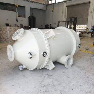
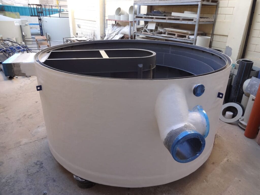
Local reinforcement can spread load over a wider shell area, reduce stress concentration, and help preserve geometry around the opening. A thermoplastic design may use a particular neck geometry, local thickness, ring or supporting structure. An FRP design may use a tailored laminate with fibers oriented for the actual load path. The selected design basis determines the required detail.
Reinforcement does not make an unsupported line acceptable. It does not remove restrained thermal growth, flange misalignment, or pre-load introduced by pulling a spool into place. If flange bolts must draw the pipe into position, the nozzle is already loaded before the system operates.
The DVS 2205 family addresses the calculation of thermoplastic tanks and apparatus, including provisions relevant to tank geometry and flange connections. The applicable model depends on the tank and connection geometry; a standard reference is not a universal allowable-load chart. For composite tanks, the principles in our FRP tank guide must be translated into a nozzle-specific laminate detail.
In other words, tank nozzle reinforcement is a designed load-spreading detail, not a generic accessory. On polypropylene tanks, neck geometry and local thickness may govern; on FRP tanks, laminate sequence and fibre orientation are part of the answer. Both need the actual load vector and load case.

Flange alignment, gaskets and bolting
A reliable flange joint needs parallel faces, a gasket compatible with the process, and bolts tightened in the specified sequence and range for that assembly. Using bolts to close a gap or correct an angle introduces sustained load into the neck and shell. Over-tightening may distort a polymer flange and compress the gasket unevenly.
Before bolting, verify that the pipe remains in position without help from the tank flange, the angular and linear offsets are within the approved tolerance, and nearby component weight is already carried by supports. After first filling and a relevant thermal cycle, inspect for leakage, flange rotation, support contact, and evidence of movement. Chemical compatibility remains part of the decision, as outlined in our comparison of industrial tank and piping materials.
This installation check is where piping loads on the tank wall become observable: forced fit-up, flange rotation, and a support losing contact are physical evidence of an unintended load path. The acceptance record should capture those observations alongside bolting and leak-test results.
The interface schedule the piping team and tank fabricator need
Good coordination starts with one data row for every nozzle. It avoids a common late-stage gap in which the tank supplier receives only a diameter while the piping engineer later asks for allowable reactions. The schedule should include:
- Nozzle number, elevation, orientation, diameter, flange standard and material.
- Fluid, concentration, density, operating and design temperatures, pressure or vacuum.
- Three forces and three moments for every relevant load case, with axes and signs.
- Expected piping movement and any predicted nozzle displacement.
- First-support location and type, anchors, guides and expansion devices.
- Weight of valves, actuators and other nearby components.
- Inspection, leak-test, access and maintenance requirements.
In wastewater service, cleaning, solids accumulation and line-opening cases may also change reactions. Our article on tanks and piping for industrial wastewater provides the process context; the nozzle schedule adds the mechanical interface for each connection.
What do our delivered projects prove - and what still needs design data?
For the Nirlat storage-tank project, we designed, manufactured and installed seven tanks: six PP tanks and one HDPE tank. The work included custom connection interfaces, service ports, structural support and anchoring, coordinated with the existing facility layout. It is a practical example of why nozzle location and support strategy cannot be treated as late additions.
On the 130 m³ HDPE tank project, custom openings, connections, service ports, drainage channels and anchoring were coordinated with consultants, subcontractors and the client's engineers. Here too, the value lies in coordinating the tank, the site and the surrounding systems as one interface.
However, the public project pages do not publish force and moment components or allowable loads for individual nozzles. They demonstrate design and coordination capability, but they are not a substitute for a new-project calculation. Every tank still needs an interface schedule that records Fx, Fy, Fz, Mx, My and Mz for each load case and the capacity accepted in writing.
A practical review sequence before fabrication and commissioning
- Define cases: empty, full, start-up, shutdown, cleaning, temperature extremes and credible occasional events.
- Calculate reactions: the piping team reports forces, moments and movements at each interface.
- Check the tank: the fabricator assesses shell, opening, neck, flange, reinforcement and anchorage for the material and design basis.
- Coordinate supports: revise routing, restraint or flexibility where reactions exceed the accepted capacity.
- Verify installation: no forced fit-up, no unsupported component weight and every support active as designed.
- Record handover: keep as-built drawings, bolting requirements, test results and maintenance inspection points.
The key handover document is not only the tank drawing or piping isometric, but the interface schedule that links them and records who accepted each load caseWarning signs on an existing installation
Repeated flange leakage, gasket extrusion, bolts that lose tension, a crack beside a weld, local whitening of thermoplastic, a changed nozzle angle, a pipe lifted clear of its support or strong vibration during start-up all justify investigation. Re-tightening alone is not the first diagnosis. The line should be made safe, supported, checked for alignment and examined for the source of the reaction.
For an existing composite tank, our fiberglass tank repair guide covers inspection indicators and repair context. A thermoplastic assessment needs to consider resin grade, weld condition, creep and service history. A local patch without removing the load mechanism invites recurrence.
Design the connection as part of the process system
A reliable tank is not an isolated product. Material, geometry, piping, supports, anchorage and operation interact. When interface data arrives early, nozzle locations can be set intelligently, reinforcement can be designed for the real reactions, and the piping layout can be corrected before fabrication begins.
If you are planning a new system or investigating a troublesome connection, send us the layout, process conditions and load schedule. We can review the interface as part of the design of industrial plastic storage tanks and their connected piping, and identify any missing inputs before production.
That interface review is particularly valuable for thermoplastic industrial tanks, where time, temperature and restraint interact. It creates one agreed boundary between the tank, piping and structural teams before site installation turns a missing design input into rework.